
Add a ‘Charging’ indicator to the Ryobi One+ 18V USB Adaptor
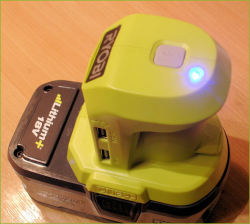 A Ryobi USB Adaptor with my LED Charging indicator modAfter nearly 20 years I’m still a fan of the Ryobi 18V One+ system that uses an 18V rechargeable battery to power a whole range of Ryobi One+ tools. In case you're unaware, you buy a 'bare tool' and buy the batteries separately. You can then use the same batteries to power 150+ tools and accessories.
One handy accessory is the Ryobi 18V USB charger (R18USB-0), which clips onto a One+ battery to provide two 5V USB ports rated at 2.1A and 1A. It’s intended to charge eg smartphones on the go but could also power other USB gadgets, LED camping lights or chargers etc, acting like a souped-up powerbank. It could also prove handy during power cuts.
The only control it has is a simple ‘start’ button on top. Once you press it, the charger powers up and automatically shuts off again 8 hours later.
This design has a major omission, though: for some strange reason there’s no at-a-glance indication of whether the charger is actually working or whether it's finished, unless the smartphone etc. being charged has an opto-indicator of its own.
I've now figured out how to add an LED Charging indicator to the USB charger to show that it's operating, an upgrade that turned out to be easier than I expected. Anyone with hobby and basic soldering skills should be able to do the same, following my outline guidance below.
Add a Charging LED to the Ryobi 18V USB Adaptor
Before you start, note that modifying this product will invalidate the manufacturer’s warranty!
You will need:
A 5V 3mm LED, ready to solder into place. These are available online from eg hobby or modeller’s outlets. (See below.)
Tools: A T15 slim-design Torx driver, soldering materials, (maybe) a hot melt glue gun, a 3mm drill bit and (ideally) a countersinking bit.
Disassembly: the plastic case is held together by four Torx T15 screws. The holes are about 6mm diameter. Also three adhesive tamper-evident labels bridge the two halves and need carefully peeling off at one end (only). The charger body simply comes apart.
Before going any further, I used a marker pen to denote the +18V battery terminal also on the plastic, to ensure it's the correct way round when re-assembled.
;) The PCBs removed [click]The USB board and power button board simply slide out.
The PCBs removed [click]The USB board and power button board simply slide out.
;) Close-up of main board - note the solder pads along the bottom [click]
Close-up of main board - note the solder pads along the bottom [click]
On examining the charger board I found a row of solder pads on one edge, which (happily) are silk-screen printed to identify them. Maybe they’re used during in-factory testing. Both a +5V and GND terminals are clearly shown, and I found that I could hook up a 5V LED directly to them, which would glow when the charger was operating. The LED only uses a tiny current which will not affect the overall performance. So I didn't see why I couldn't solder an LED (the right way round) directly to those two pads to act as a Charging indicator.
I reckoned the best location to fit the LED was near the power button, where there’s a little bit of clearance for the LED and its wires. Using a 3mm drill bit, a mounting hole was drilled through the case in the location shown, which I finished off with a countersinking bit to create a nice recessed bevel effect. It looked very professional!
;) 3mm hole drilled and bevelled for a neat effect
3mm hole drilled and bevelled for a neat effect
;) 3mm colour changing LED pre-wired for 5V use [click] LED wiring: As I couldn’t be bothered making up an LED myself, I found a 3mm RGB colour-changing one with ample connecting leads and series resistor, and red/ black flying leads to identify polarity. It was pre-tinned and ready to go. It cost about £3 for a pack of five.
3mm colour changing LED pre-wired for 5V use [click] LED wiring: As I couldn’t be bothered making up an LED myself, I found a 3mm RGB colour-changing one with ample connecting leads and series resistor, and red/ black flying leads to identify polarity. It was pre-tinned and ready to go. It cost about £3 for a pack of five.
To connect the LED, solder the red (anode) and black (cathode) wires to the +5V and GND solder pads respectively.
;) LED mounted near the power button [click]
LED mounted near the power button [click]
The LED can then be inserted into the plastic housing. As I hoped, my LED was a tight push-fit into the 3mm hole (I used some long-nose pliers to fit it in), and a dab of glue was all that’s needed to keep it in place. Then route the wires inside and around the PCB, dodging the internal fittings when the two halves are re-assembled. Some dabs of hot melt glue may help keep the wires in place.
;) The LED soldered to the board [click]Re-assembly: The rubber power button fits one way round (there’s a notch), but ensure it’s the right way up, too! Lastly, re-fit the battery connector board, then ‘dry-fit’ the two halves before screwing them back together.
The LED soldered to the board [click]Re-assembly: The rubber power button fits one way round (there’s a notch), but ensure it’s the right way up, too! Lastly, re-fit the battery connector board, then ‘dry-fit’ the two halves before screwing them back together.
;) The LED installed ready for re-assembly. The half-peeled off labels can then be stuck down again.Test it on an 18V battery – press the power button and the LED should light, press again to switch it off. Then you can re-fix the three labels using a dab of eg UHU or Bostik if necessary, and the job is done. Now you have a handy USB adaptor and you can tell at a glance whether it’s timing or not!
The LED installed ready for re-assembly. The half-peeled off labels can then be stuck down again.Test it on an 18V battery – press the power button and the LED should light, press again to switch it off. Then you can re-fix the three labels using a dab of eg UHU or Bostik if necessary, and the job is done. Now you have a handy USB adaptor and you can tell at a glance whether it’s timing or not!
The finished job looked really neat and you’d never know that it was a DIY mod. I liked the slow colour-changing LED which gave a 'breathing' effect. The countersunk bevel also produced an ideal viewing angle of nearly 180°, and my LED is visible from 20-30 feet away.
I sourced the LED from eBay. Search for 5V 3mm Wired LED Modeller LED. You can of course just use a standard colour LED, or wire up your own with, say, a 560 or 680 ohm series resistor the usual way.
Ryobi R18USB-0 18V ONE+ Cordless USB Charger (Body Only) - https://amzn.to/3wXoWS6
Ryobi RB18L20 18V ONE+ Lithium+ 2.0Ah Battery - https://amzn.to/3PszzlY
Torx Hex Key Wrench Set, T10-T50 Long Reach L-Shape - https://amzn.to/3PsdR1F
T15 Torx Star Key L-Shape Long Reach (2 pcs) - https://amzn.to/3VpqnTo
The above Amazon Affiliate links help towards the running costs of this web site.
- The LED was supplied by the UK eBay seller Electronic Repair Store

 Hobby Electronics tagged
Reader Comments