PURE Avanti Flow – replacing the OLED display
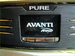 An Avanti Flow with new OLED display
Latest sources of suitable OLEDs for PURE Evoke Flow / Avanti Flow
Please read the latest news on my Pure Evoke Flow pages, where the majority of interest is.
The recommended source of replacement displays (white only) is Alibaba - please read all the comments carefully for advice and feedback about 'buying direct' instead of via the Alibaba portal.
Many folks report good service and good quality high-brightness displays, delivered quickly:
On Alibaba - Shenzhen Liyuan Huida Technology Co (Jack Wan) offers some new stocks of higher brightness OLEDs and are known to offer a good service to UK individuals. Many people say they have been very successful replacements recently. See https://www.alibaba.com/product-detail/22pin-yellow-white-3003319301002-Pure-Evoke_60671545961.html
I recommend reading all the user comments on my Evoke Flow repair pages as this used the same display.
SOME EARLY REPLACEMENT OLEDs BOUGHT FROM BULGARIA and ITALY CAUSED PROBLEMS WITH MIRROR IMAGE DISPLAYS - PLEASE READ THROUGH THE [Evoke Flow] COMMENTS SECTIONS CAREFULLY TO AVOID BUYING PROBLEMATIC ONES.
-- ARW
I’ve had lots of requests asking about replacing the OLED displays in a PURE Avanti Flow tabletop receiver. Since I had a spare (white) OLED display left over after repairing my portable PURE Evoke Flow, eventually I sourced a used, working Avanti Flow which needed a new display. It’s a very common problem: the working life of these OLED displays is about 30,000 hours so they just wear out over time.
Before you start
Note that some owners reported it was straightforward to swap the display by taking out the front panel; I think they were quite lucky, as some users still ended up having to access the insides by dismantling everything from the REAR anyway, as shown in my full photo sequence. And if ribbon cables become disconnected internally, you'll have no option but to take the whole radio apart anyway to reconnect them. Don't be put off, as a successful repair is achievable either way, with care.
The Avanti Flow can be much trickier to repair than a PURE Evoke Flow because it contains a sandwich deck of printed circuit boards, each connected by a spaghetti of ribbon cables all located in a restricted space. In my case [working from the rear panel] I needed a number of electronics tools to reach around and manipulate cables and connectors, and the work was more like keyhole surgery at times!
Some users say it was not easy that way, but they got there in the end. Others struck lucky by removing the front panel instead, simply needing to modify the plastic panel very slightly to hold the new display (see comments).
Despite everything I was pleasantly surprised that I managed to get mine working first time and it now sports a new white OLED display. What follows is a general guide only to give you an idea of what's involved. I have tried to cover everything but I don’t guarantee I covered every last little thing, nor in exactly the right order, and I’m not responsible for anything that’s been left out. Hopefully without explaining the ‘baby steps’ my photos and text will show a skilled tech. an idea of what’s involved so you can decide whether to tackle this job yourself. As far as I know there is no such guide about the Avanti Flow anywhere else online.
You will need to set aside some quality time (up to 2 hours), working carefully and delicately, while being vigilant and observing the routes of all ribbon cables and cable headers closely to ensure you can disconnect and reconnect everything properly. It’s hard to replicate a multi-million dollar factory at home but a number of tools will be needed and you’ll also need to be patient and pretty resourceful to complete the repair successfully. It's tricky, but having said all that, it can still be done successfully!
Opening up an Avanti Flow from the rear
I am guessing that the radio internals are pre-assembled on the factory bench before being fitted into the cabinets. At that time, I could not figure out how to access the display from the front as the front panel and speaker grille were very secure with invisible fixings at each corner. Much later it was found that it slides out if you grip the grille carefully with eg electronics pliers. Not wishing to damage the grille I started from the radio’s rear panel instead. If you start from the front, and some ribbon cables become disconnected internally, you'll have to open up the rear anyway to reconnect them.
 Remove 8 x Phillips screws [click to see]
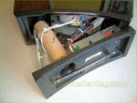 The rear panel removes easily and can hang out [click to see]With the radio face-down on a cloth, start by removing 8 x Philips screws from the rear panel. The rear will then lift out completely and can be swung to hang over the edge. It also carries the power supply and bass port tube.
 Rear panel hanging down before removing the sub woofer [click to see]Reach inside the radio and use radio pliers to unhook the 2 x leads from the sub-woofer speaker. Remove the acoustic wadding.
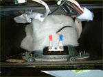 Sub woofer terminals can be removed next [click to see]
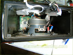 Internal view after removing acoustic wadding [click to see]
Remove the sub woofer
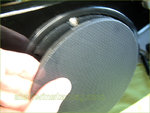 The speaker mesh can be prised out carefully [click to see]
 ... revealing the sub woofer [click to see]Underneath the radio, the speaker mesh is a simple interference push-fit and can easily be teased out with eg a pointed probe. Then remove 4 x Philips screws (15mm long) on the speaker plastic mounting ring, and then unscrew the sub-woofer (4 x 10mm screws) and extract the speaker from inside the radio. This makes the interior accessible.
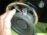 Then the sub woofer can be withdrawnReach through the speaker cut-out and unscrew 2 x nylon P-clips that secure wiring looms to the cabinet; some black foam rubber ‘shims’ were removed from ribbon cables next.
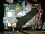 First glimpse of the radio board, the first PCB to be removed [click to see]The Avanti Flow carries a stack of circuit boards inside the cabinet: first is the radio board, underneath that is the audio board and finally the display/ front panel switch board is fixed right at the bottom. They are all interconnected with various ribbons and wire connectors and they all mount on plastic pillars using self-tap screws.
Radio board
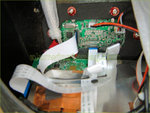 Radio board with copper-screen ribbons x 2, and ipod dock above (and more ribbons!) [click to see]The radio board is held with 4 x 8mm long self tap screws, one screw also traps a (solder tagged) shielding wire hooking to the PSU screen. I used a long-reach electric screwdriver with a (magnetic) Philips tip to remove the screws successfully. You don't want to be dropping them inside the radio.
Unhook 2 x ribbon cables on the ipod dock. They will simply pull out and they connect to the main board.
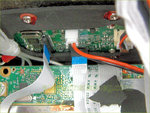 Remove the ipod dock ribbons and pin header [click to see]The radio’s two main wire looms are an obstacle: stiff and inflexible, they obstruct the removal of the boards, but you can cut off any nylon tie-wraps to loosen up the wiring. I cut off all the tie-wraps.
Gently lift the radio board away a little, I moved it to one side. Two ribbon cables (10mm and 15mm wide) are shielded with copper tape; these go to the OLED display board at the very bottom of the radio, so unpick the copper foil and unhook both ribbon cables. (That’s because later I saw it’s easier to unhook these two ribbons from the 'radio board end' and leave them connected to the display board. Otherwise you will need eg a long-reach flat-bladed tweezer to reconnect them to the display board (which luckily I had!) once in situ. My photos however show these two ribbons as disconnected from the display, not the radio board.
 The radio board partly removed. See text re. the two ribbon cables [click to see]
Audio board
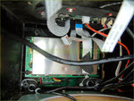 The audio board is revealed [click to see]
Disconnect 2 x header wires on the radio board and lift it away to reveal the audio board under it. Note how a short 20mm ribbon is fitted between the radio board (underside) and audio board (top side).
 The audio board lifted slightly, note the headers underneath [click to see]The audio board is held down by 4 x black self tap screws. Disconnect 2 small pin headers along one side (3-pin and 4-pin – see how a very short wire disappears inside into a front stereo speaker), and then disconnect a 3-pin and 5-pin on the board’s longer edge.
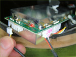 Reach through the speaker cutout and unhook the headers - I marked them with Sharpies to colour-code them [click to see]
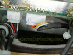 Disconnecting the audio board [click to see]This leaves three 3-pin headers on the other short side of the board. I used coloured Sharpie pens to mark which cable plug goes into which header. See again how a very short cable disappears into the cabinet to the other front stereo speaker. The other two cables carry ferrite cores which are a nuisance, but they slide back up the cables out of the way. Having colour-coded the wires, unhook them from the audio board and gently remove it or set it to one side.
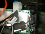 3 x pin headers (inc. one stereo speaker), mark them and remove [click to see]
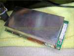 Audio board removed [click to see]
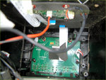 The display board revealed [click to see]
 The OLED display/ switch panel removed [click to see]
Display board
With the audio board removed, the OLED display/ switch is revealed. It has 6 x self tap screws and another 10mm ribbon cable. Taking this apart, the OLED itself can be lifted off, helped by e.g. a right-angled probe.
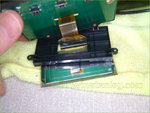 Separating the display [click to see]The OLED display ribbon clearly shows pins 1 and 22 and the ribbon cable can be disconnected from the PCB header by gently sliding out the ribbon connector’s black plastic holding clamp. (See my Evoke Flow guidance and photos for more details – it’s the same connector).
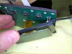 Preparing to disconnect the old display [click to see]
 The flat ribbon latch (black plastic) is very delicate [click to see]
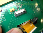 Disconnected, note the pin labels 1 - 22Remove any protective poly film off the new OLED display and clean the front display window. The new display ribbon is passed through the mounting frame the same as before. My (white) display was a direct replacement, the same shape and ribbon orientation.
Unfortunately it would be easy enough to get a new display upside down or the wrong way round and you would never know until the radio was assembled again, so take some photos if necessary to remind you of the display’s orientation. I also used two small dabs of glue to hold the new OLED on its black plastic mounting frame. Unlike the PURE Evoke Flow, everything is located securely in place with no scope for misalignment. More recently, it's been found that the plastics needs altering slightly to carry the latest OLED boards.
The PCB also carries the front panel push switches and an LDR (light-dependent resistor) which must all align properly with the front fascia and its buttons.
Reassembly
With the new OLED fitted and the display board screwed back in place, the audio board can now be reconnected which is easier said than done. There are no less than seven PCB headers to reconnect and it’s also easy to get the board the wrong way round in situ.
 Re-installing the audio board and its wiring
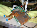 I'd left my radio board hanging around, partly connected. See text about those two copper-clad ribbons [click to see]Don’t overlook those two (15mm and 10mm) ribbons that stem from the display board and go ‘past’ the audio board to the radio board above it. Of course, ensure all ribbon cable conductors mate with the corresponding PCB header properly: the metallic conductors can be seen and they must mate together when the ribbon is inserted into the connector.
I used flat-bladed radio tweezers (similar to ‘postage stamp’ tweezers) to grip and slide the ribbon cables back into their headers successfully. This worked extremely well.
 The audio and radio boards back in situ [click to see]Probably the hardest part was re-connecting the audio board leads, which I found very fiddly and time-consuming. I used a variety of long-nose pliers, bent-nose pliers, hooked probes and a lot of dexterity to hook them back UNDERNEATH the audio board (which lies component-side down), but it was possible with care and a lot of keyhole surgery. Definitely not a job if you have ‘sausage fingers’ but it can be done. Slide those ferrite cores back up the wires out the way, if necessary.
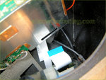 This short 20mm wide ribbon connects the audio and radio boards [click to see]
Re-locate the radio board in place, reconnecting a short 20mm wide ribbon on its underside to the audio board located underneath. The ipod dock ribbons can also be reconnected.
The ‘memory’ of various wire cables helped with routing them to the relevant headers on the radio board and it was fairly straightforward to re-connect everything else. Soon I was only left with the sub-woofer cables to hook up, so the speaker and grille were refitted and the sub-woofer was finally reconnected.
I decided to leave off all P-clips and nylon tie-wraps, leaving the wires routed loosely inside. The acoustic wadding was put in again and the case rear was closed up with 8 x screws.
I did notice white specks of dirt etc inside the display window (not on the new OLED), which is a shame but I decided to leave it alone as it’s an old radio anyway and I just wanted to prove a point. Power up time... would it work?
Powering up again
Every electronics hobbyist knows the feeling of anticipation when powering up their project for the first time. Switching on at the mains and after a few seconds I was rewarded with the Avanti Flow splash screen (in white) followed by Initialising...... and then the radio burst into life. I’m thrilled to say the repair was entirely successful, and the radio could be retuned to local DAB stations without a problem. All buttons and menus worked as expected.
 After a few seconds, the splash screen appeared [click to see]
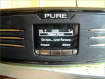 Tuning in... [click to see]
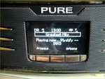 More stations... [click to see]
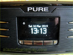 Standby screen [click to see]
Replacement OLED displays are getting harder to source, but those purchased via Alibaba seem to be the best quality. I can only re-iterate that the Avanti Flow is a very fiddly job best undertaken by those who are used to fiddling with electronics and manipulating wires and PCBs. With the right skills, patience and tools it’s entirely possible to fit a new display to an Avanti Flow as I hope the above photos prove.

 Alan W
Front speaker grill removal
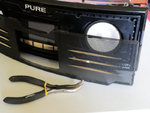
After a reader tip-off I managed to removed the front grille - Doh! - it simply prises out (the metal mesh only - not the plastic surround) by gripping one of the silver plastic 'fins'. Or you could try using a bent paper clip or hooked wire on the grille. Then 8 Philips screws can be removed and the entire front speakers / display assembly will start to come out - but not all that far because of the internal cables.
I am loathe to try removing it, because some of the ribbon cables don't have much 'slack' in them to allow withdrawal, so if you accidentally yank them out from within the cabinet you'll have to start disassembly all over again from the rear of the cabinet, which would be quite a fraught job. At the moment I can't recommend trying to swap the OLED by accessing it from the front. AW
 Alan W
Update 9th September 2020
Fix from the front or the back?
There's still some debate about whether to swap the Avanti display by removing the front or go in from the rear panel like I eventually did, per the photos. The front panel is easiest, but I felt that there was a lot of scope to accidentally pull out the ribbon cable and if it disconnects internally you will have to open up the radio from the rear panel and reconnect it that way. So you could try it from the front first and see how far you get - the choice is yours!
 Alan W
Avanti Flow v5.1 firmware update
The final software version was V5.1 but (typically) PURE has 404'd their support page for this update.
I found it on Archive.org here (Mac & Windows) (Active 30th April 2023)
My radio wouldn't connect to wi-fi so I had to update via Windows and a USB cable, a slow but successful process. My radio now works as expected, hooking to my wi-fi successfully but because PURE dropped its web access the former owner's 'Lounge' folder and favourites can't be changed. AW

Reader Comments (32)
This is fantastic, thank you so much. Think it will take me more than 2 hours.
Kind Regards
Bob
Thanks for the post - would not have even started this without all your help. I found however that it was really easy to open the front - I just used a pair of pliers on the "fins" on the speaker grill and out it popped - very easily. Then rather as for the rear there are 8 screws to remove and access is given to the board set from the front. This made some re-attachement jobs - such as the ribbon between the radio and audio board - much, much easier to do. However my new display is not (yet) working - but hopefully now I can assemble and disassemble without 100 years experience of key-hole surgery - I'll find what is wrong. The new display (from Italy FC components) is a little larger than the old one - but still seems to fit in place. Again thanks for the excellent article. Dave
I looked at mine again and you're right -- the metal mesh (but NOT the surrounding plastic frame) did prise out by gripping the silver fins on one speaker using eg radio pliers. Then the grille could be removed.
I'm a bit bothered that if you pull out the display ribbon cable from within the radio then you will still have to open it up from the rear, also there did not seem to be much slack to allow a repair from the front. It's something I'm looking into. Keep those comments coming!
Where can I purchase a new digital display for the Pure Avanti flow? Please
Thanks for this. It gave me sufficient confidence to have a go and thankfully I still have a working Flow but now in "white".
First components delivered quickly but at significant cost.
Comments would be that the first components oled is slighly bigger than that originally fitted to the flow so I needed to trim the plastic at the corners of the mount slightly but this was easily achieved with a craft knife.
I started by undoing the screws that hold the front in then started from the rear as described above. Once the radio and audio board were out I then pulled the front out which gave easy access to the display board and the display. I found re-assembly straightforward as I put the radio board on before putting the front back in. The only issue with that was making sure that the two ribbon cables didnt get caught as I slid the front in. Doing it this way meant that the only really awkward cable was the ribbon between the back of the radio board and the audio board.
Don't forget the orientation of the subwoofer as it goes back in i.e. terminals to the left or right.
It took a good length of time but I only really used one screwdriver and one pair of long nose pliers.
Again the process description above was invaluable in getting me going. Thank you.
Hi Alan, just wanted to thank you for the detailed instructions. My screen started dimming all of a sudden a couple of months ago and a quick Google led me here. As above, this gave me the confidence to give it a go.
I bought a yellow LCD screen off eBay for about £50, and got stuck in! I took the front and back of my flow and after a few hours, lots of photos and careful reading of this page it worked first time, phew! I don't have much experience disassembling electronics but found it all pretty straight forward. Trickiest bit was removing the old screen from the plastic mount since it was glued on and the glass shattered as I prised it off. Took a while to clean off all the glass shards but after that, reassembly was pretty easy. As per Carl's comment above, taking the front off made it much easier to get the screen out and back in after the other boards were removed.
Thanks again, my faithful avanti flow now lives again (hopefully for another 10 years!).
Thank you for your detailed instructions on how to replace a Pure Avanti Display. I received the display from First Components (64 euros,) and managed to replace it after struggling for about 4 hours. The plastic holder for the display needs to be modified with a small file because the replacement display is about 1mm. bigger, so DON'T TRY TO FORCE IT. Incidentally, I spoke with PURE customer services and they weren't interested in helping with this display issue.
Glad it's all working again for you, note that PURE got taken over a few years ago and sadly the current owners won't be interested in supporting legacy products like the Evoke and Avanti Flow. Also, it's a case of getting replacement displays while you can. First Components seem to be dealing with this very well judging by feedback, but the OLED cost is not exactly trivial. AW
Many thanks for this post!
Would not of tried swapping out the screen otherwise!!
First direct screen fitted ok. on reassembly the buttons did not work.
stripped and reassembled still no response from the controls.
used my own photos for the ribbon orientation and seems ok and fully located.
luckily the remote operates the unit fully.
Any suggestions to might what be wrong?
thanks.
Tom.
(Avanti Flow?) if it was working before then I suspect a ribbon cable must be astray internally or the wrong way round, or not inserted fully, there's nothing else it could be really. The Avanti Flow is very tricky to work on in that regard, as I mentioned in the article.
Just replaced the oled display from my Pure Avanti Flow. Opened both sides. New display from First Components.
Thanks for these posts. My Avanti flow display has died too and these posts are steering me towards trying to change the display despite not having any previous experience in this 'stuff'.
My big problem is that I can't locate any replacement displays. Anyone know any current suppliers?
Thanks a lot.
First Components
Some report First Components in Italy had no more stock, the other source is via Alibaba - check my links at the start of the blog, also see my item on repairing the Pure Evoke Flow, which used the same display.
Great explanation of how to carry out this repair.
Got my new screen from Alibaba and fitted it today in about 2 hours. Did the job entirely from the front. If you snip off all the tie wraps it will you get a bit more room.
Only problem I had apart from my spade like fingers was that the new screen was about 2mm wider which necessitated carefully removing four little plastic registers from the screen surround with a craft knife.
Great feeling when the screen and sound spring back into life.
Hope this is helpful to others.
Thanks for this info Alan - I found your site after the screens on my two Avanti Flows completely failed within a couple of months of each other. After reading that a repair was feasible I ordered replacements from Jack Wan which arrived very promptly. Unfortunately they were from a new batch and were mirrored on the Avanti. Jack sorted the issue easily though - he got a new batch of the correct displays and sent two more to me which again arrived really quickly - less than a week. These work great.
After doing two machines I can say without hesitation that working from the front is much easier than working from the back! You must have the patience of a saint to do have completed the repair from the back. Like anything else it gets easier the more you do this - I've bit done the repair three times counting replacing the mirrored display. The first time it took me two hours. The last time it took me 35 minutes. Thanks again - i would have just replaced the machines i think If I had not read your excellent article.
Do you have any idea if this display could work for the Pure Avanti Flow? I am not sure about the number of pins that are required.
http://www.farnell.com/datasheets/2723636.pdf
The Farnell device has 31 pins so cannot fit. All sorts of other problems exist such as the controller chip and pin orientation.
Yes, I too found this very helpful. I use my Avanti Flow a lot via a blue tooth receiver connected to the Aux input. I think I would have baulked at this job without reading your information. I started from the back and after removing the radio and audio boards realised the front offered a much easier route for the display board and reassembly.
A plastic coated small paper clip pulled the front grill out without marking it. I was wary that pulling on the fins would scratch them.
I also used the new screen from Jack Wan. It too is 1 mm wider than the original but easily inserted with the modification of the holder described.
The new screen displays text in green which is fine.
Thanks for your help!
I followed the instructions which were very detailed but being an absolute novice with anything electrical I gave up after fixing the display back in place. I couldn't reconnect the cables to the audio board and couldn't remember where one or two ribbons went so looks like it's going in the bin.
After successfully replacing the display on my Evoke Flow I guess I just got carried away and thought the Avanti would be as easy. Lesson learned.
Sorry to learn about your disappointment, though I did warn at the outset that it's much more complicated to fix an Avanti Flow if you've no experience of handling modern electronic boards. Some people state these radios can be fixed from the front instead, but I felt you can accidentally pull a ribbon cable out from inside and create more problems. There aren't that many different ways to connect the ribbons so I think you have nothing to lose with some trial and error comparing my photos. The display can also be re-sold on ebay for example.
Hi, I've got an Pure Avanti Flow radio, I cannot connect to WIFI, do you know where I could download the final software version V5.1? as Pure have removed from there site.
Thanks
@Dinesh
David Pye has managed to host the last firmware versions for the PURE Evoke, Avanti and Oasis, they are downloadable from http://www.davidmpye.com/files/pure_fw/
AW
I really appreciate all you work you put into making this guide. It helped me successfully replace the screen in my Avanti Flow without any qualification in the field. I ended up also opening up the front of the unit when it came to removing the pin headers from the audio board, as I found them difficult to access. As others have commented above, the screens provided from the Alibaba link are about 2 mm wider than the original, and therefore require modification to the mounting frame. This can easily be achieved by removing inner plastic ridges (vertical) from the frame. The outer edges will provide a good fit for the wider screen, with about 1 mm excess space.
In short, a complete amateur can replace the screen with enough time and patience, thanks to the instructions of this excellent guide.
Thanks for the info Alan and everyone else. I got a screen off Jack at Alibaba about half a year ago, but fitted it today. Went in from the front, but took the back off and released the black earth wire from the rear cover going to the main pwb. One ribbon cable for the iPod dock came out so I would suggest freeing up the ribbon cable bundle when you start taking it apart. Nice new white pmoled screen, well chuffed